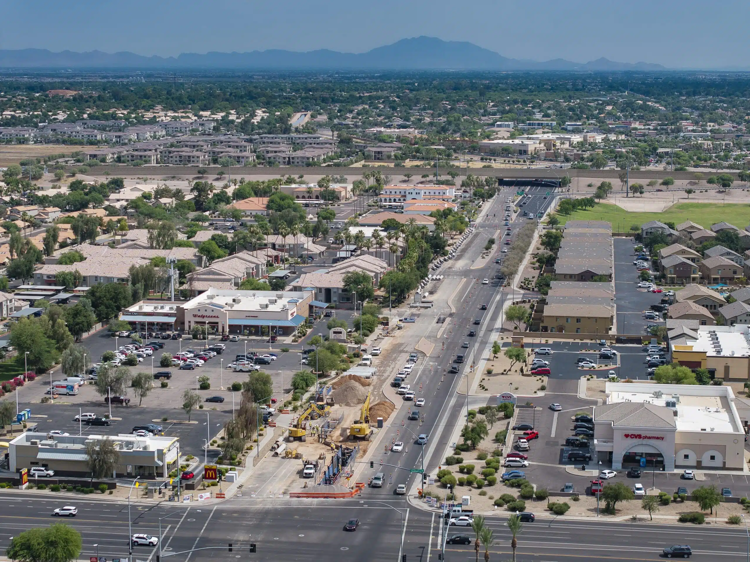
Kimley-Horn coordinated closely with stakeholders and partners to design a new reclaimed waterline in Mesa, Arizona, and...
Strategic Collaboration
Collaborated with the United States Army Corps of Engineers (USACE) to design and review pipeline alignments to find the best option for both Forth Worth and USACE
Industry Impacts
Trailblazed unique inverted siphon design, documenting methodology and contributing to future projects throughout the water/wastewater industry
Technical Expertise
Leveraged trenchless technology experience to perform open-shield pipe jacking for sanitary sewer pipeline relocation, including river and levee crossings
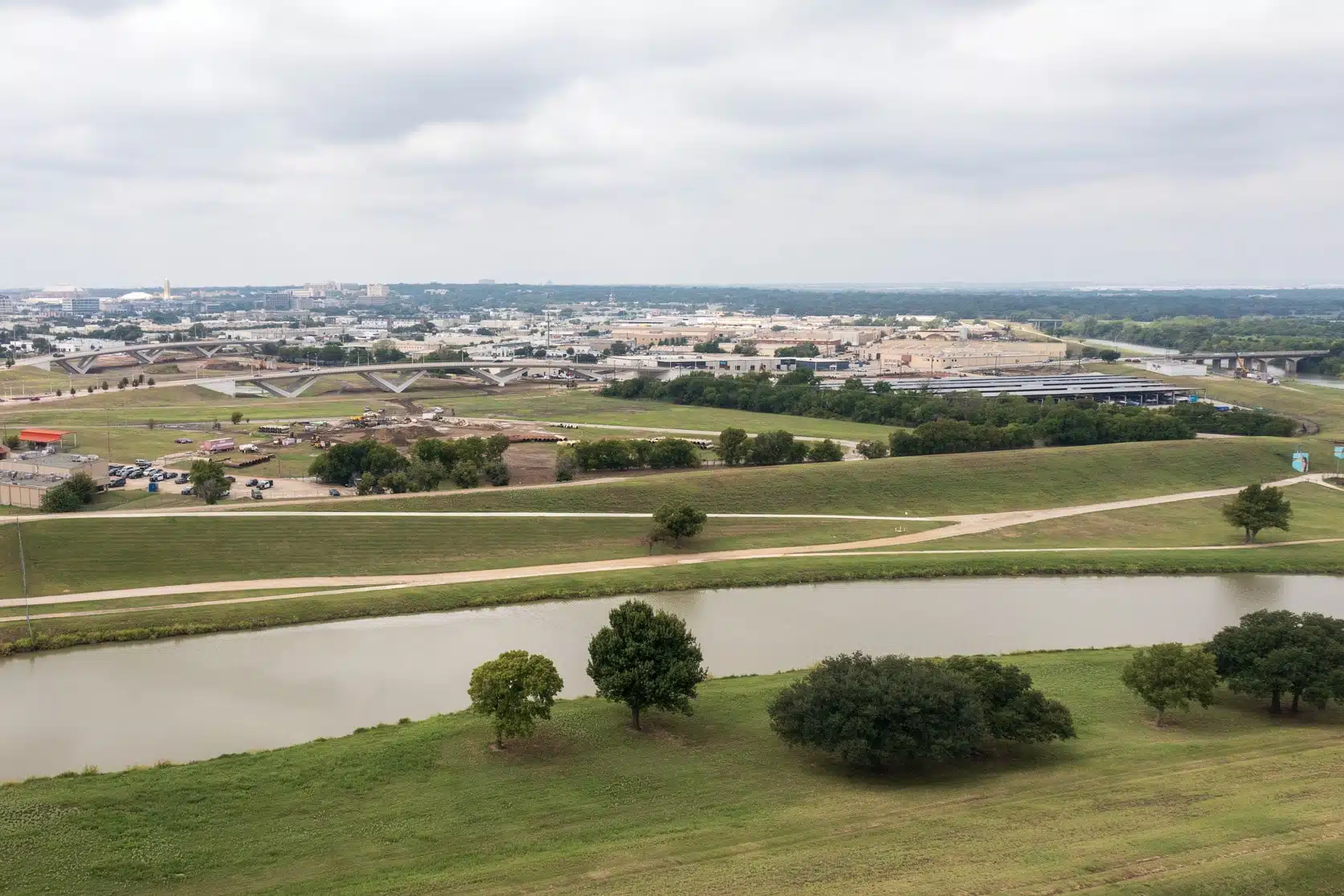
After Hurricane Katrina, USACE began investigating their levee systems and demonstrated that the City of Fort Worth levees would need to be raised to mitigate flooding concerns and accommodate the Standard Project Flood (SPF). To boost economic development and accomplish their goals, USACE and local partners crafted a new strategy, the Fort Worth Central City (FWCC) project, which will include a new river bypass channel, flood gates, and additional valley storage. The FWCC will also decommission a large portion of the levee system directly north of downtown Fort Worth for development of riverfront property in a formerly underutilized area of the city.
The City of Fort Worth agreed to perform the necessary water, sanitary sewer, and storm sewer infrastructure relocations to accommodate the FWCC, and Kimley-Horn assisted them with relocating pipelines impacted by the FWCC project, providing the following services:
- Pipeline design and routing
- Trenchless design
- Hydraulic analysis
- Inverted siphon design
- Resident Project Representative (RPR) services
Selecting a Strategic Pipeline Alignment
Our team evaluated approximately 20 alignment options throughout a year-long period. For these alignments, we considered various diameters of steel casing pipe, locations in the Trinity River area, and trenchless methods—including horizontal directional drilling, open-shield pipe jacking, and microtunneling.
In close partnership with USACE, we chose the final alignment: more than 6,000 linear feet of sewer line ranging from 24-66 inches in diameter. This alignment traverses the Trinity River and avoids costly utility conflicts and additional complexities with other alternatives.

Designing Back-to-Back Inverted Siphons
Due to existing upstream and downstream pipeline elevations, the final pipeline alignment needed to accommodate two back-to-back double barrel inverted siphons in place of an existing single-barrel inverted siphon. The pipeline will connect to an existing 66-inch interceptor on the upstream end, cross under the West Fork Trinity River via a new double barrel inverted siphon, take on additional flow from an existing 54-inch interceptor, cross an existing earthen levee, drop into another double barrel inverted siphon to cross beneath the future bypass channel, and finally connect to an existing 66-inch interceptor on the downstream end.
Based on the beginning and ending points of the relocation, only 1.7 vertical feet were available to split between both inverted siphons to accommodate anticipated headloss through each. To improve the design, Kimley-Horn developed a program to calculate theoretical friction slopes for each siphon design compared to normal flow depths. This program also helped us determine whether upstream surcharge would occur and if it would dissipate or have a tailwater impact on the next siphon upstream. We also evaluated potential surcharge to determine if additional upstream impacts on the existing system would be likely.
Developing Inverted Siphon Best Practices
In navigating the unique challenges of this project, our team developed several best practices for inverted siphons. The practices have already been used to inform design methodology on other projects, and they include the following guidance:
- Calculate head losses using a combination of Manning’s and Bernoulli’s equations and solve simultaneous equations to determine flow split between larger and smaller pipelines.
- Design upstream splitter structure with an internal weir to convey all dry weather flow in the smaller barrel and to permit peak wet weather to spill over the upstream weir into the second larger barrel.
- Design for stop log channels to permit barrel isolation for routine maintenance.
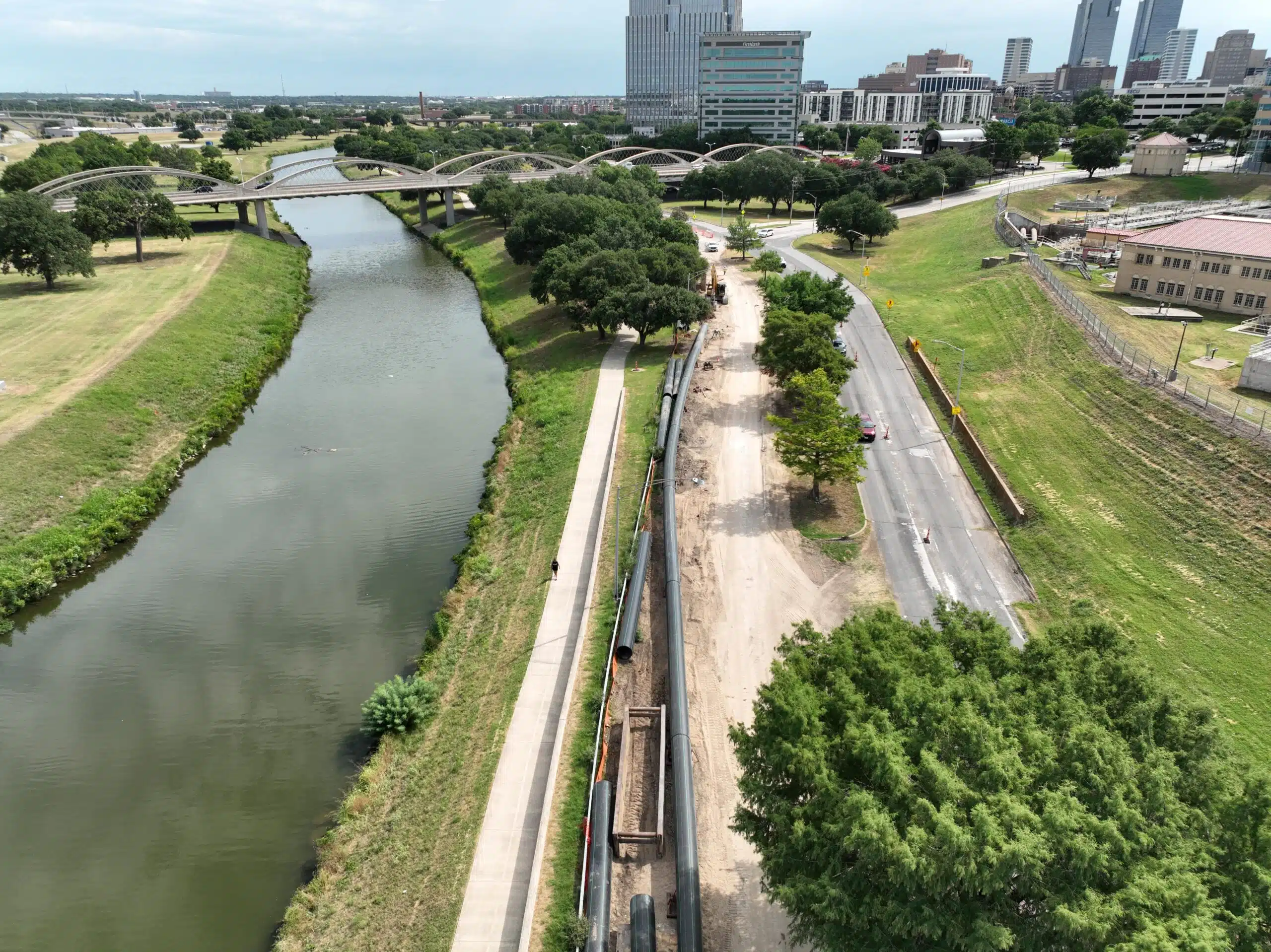
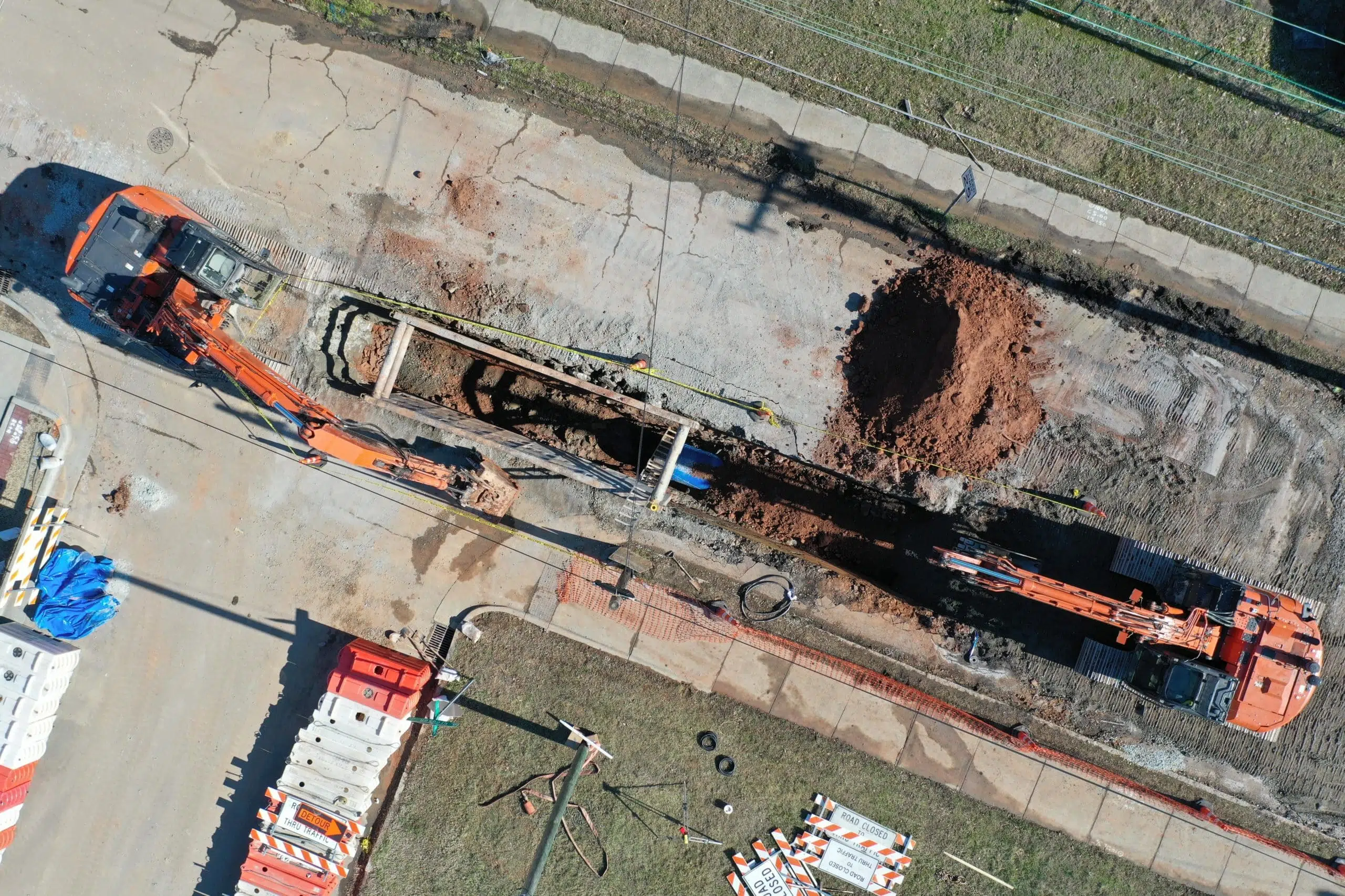
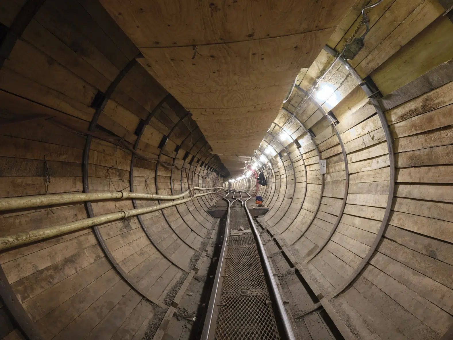
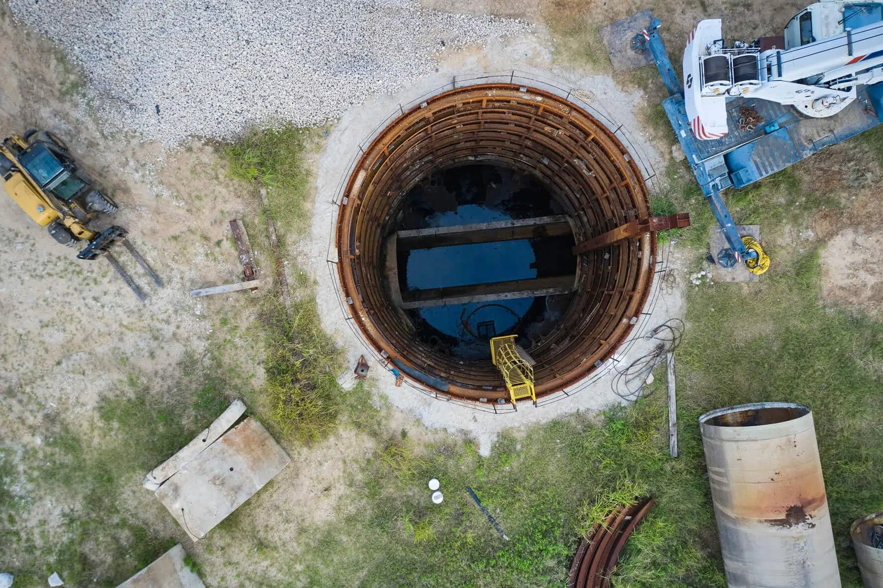
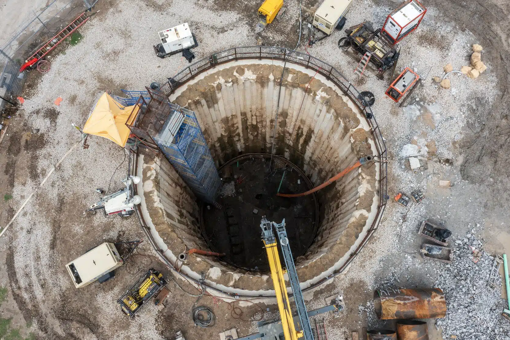
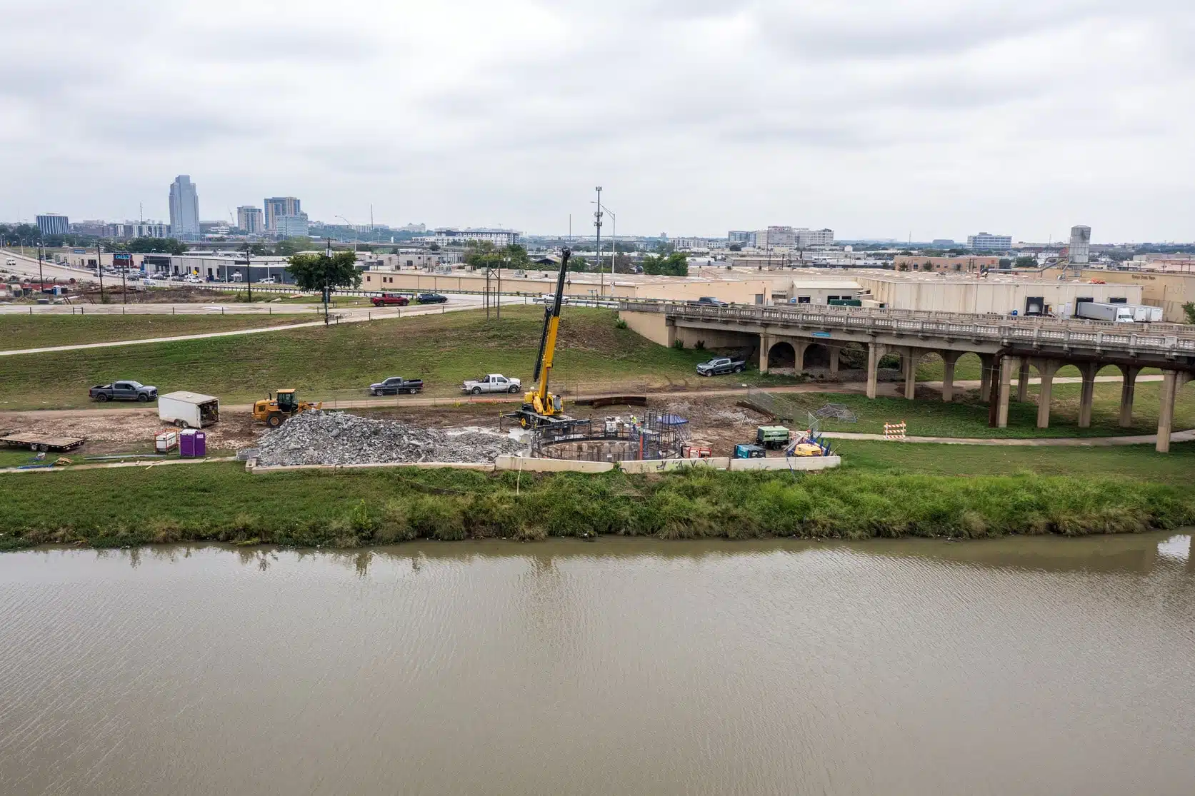
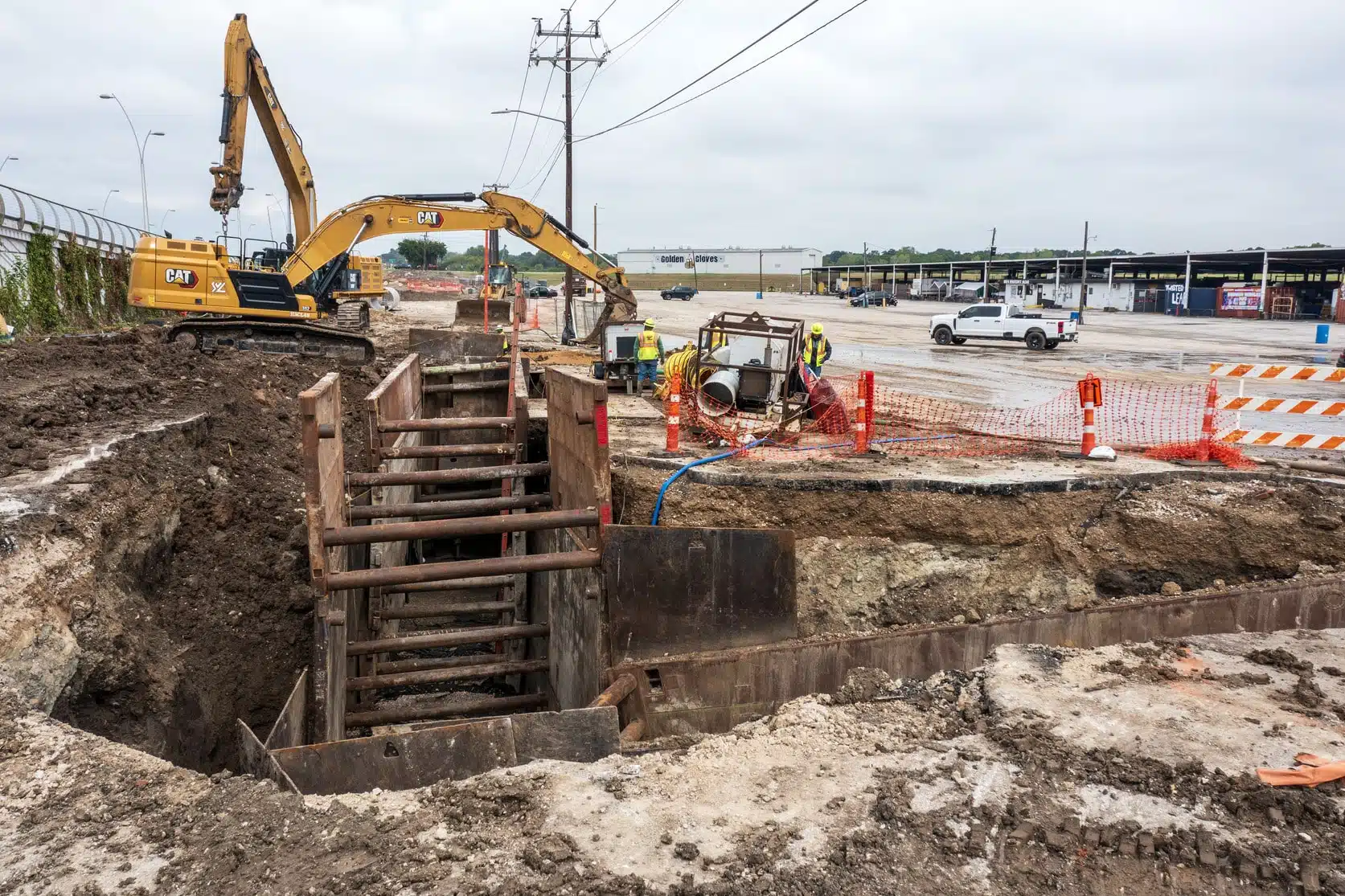
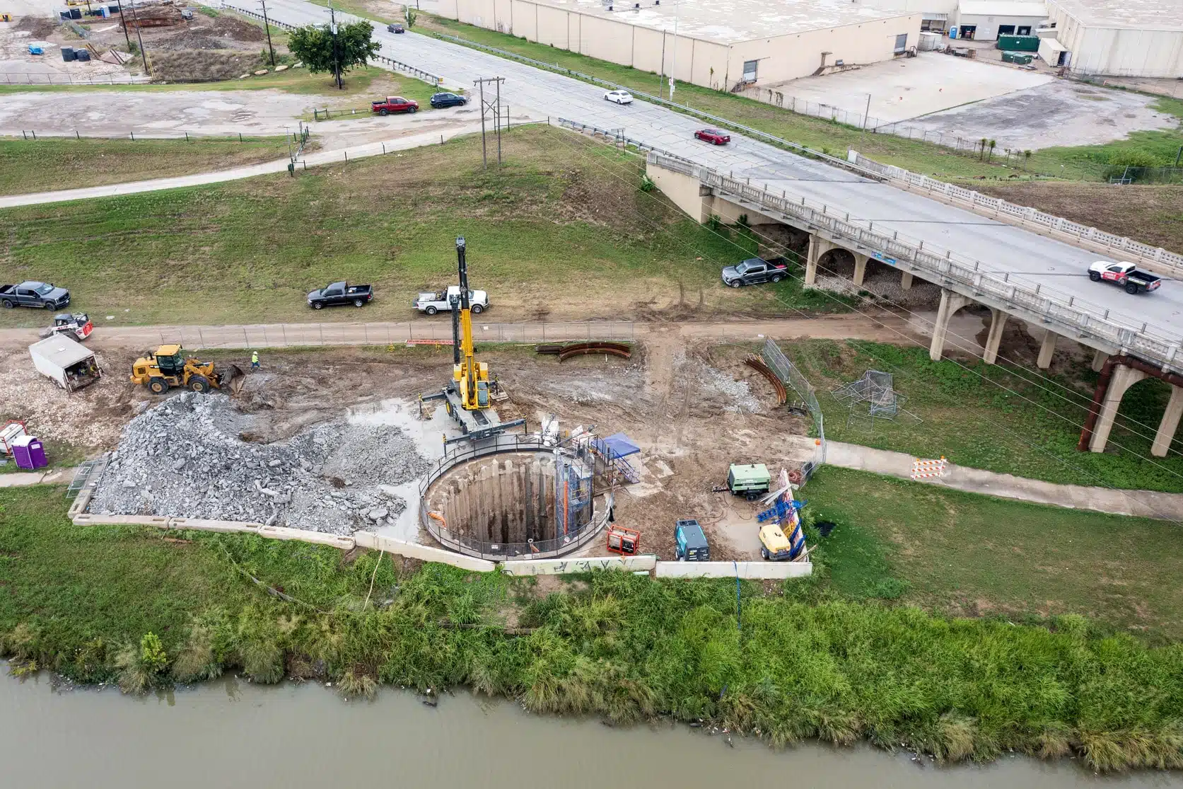
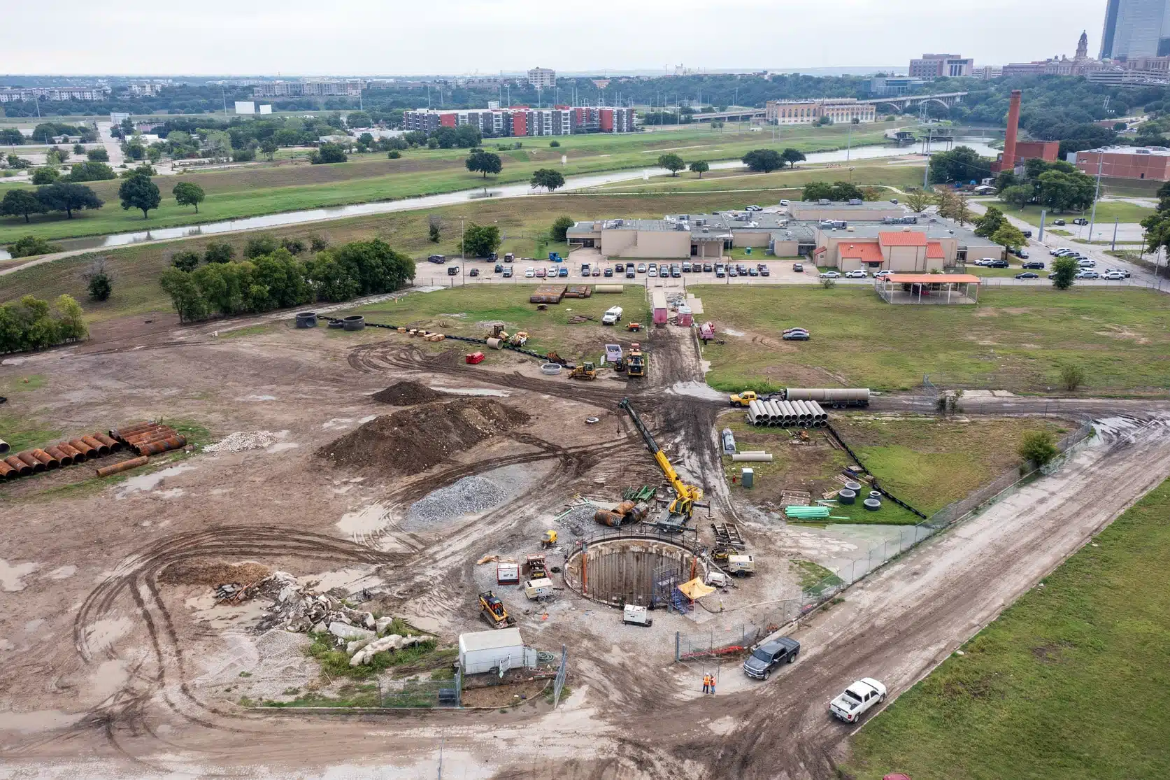
Tunneling and Challenging Geotechnical Conditions
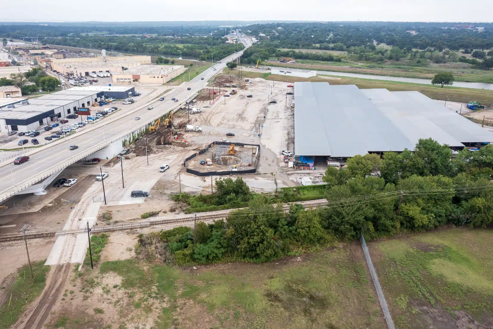
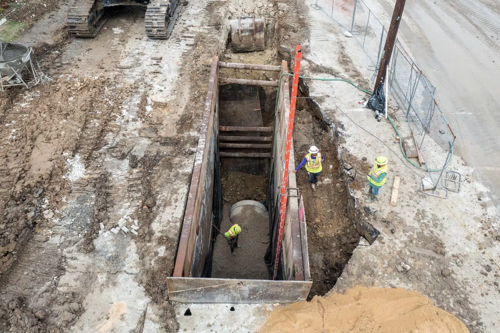
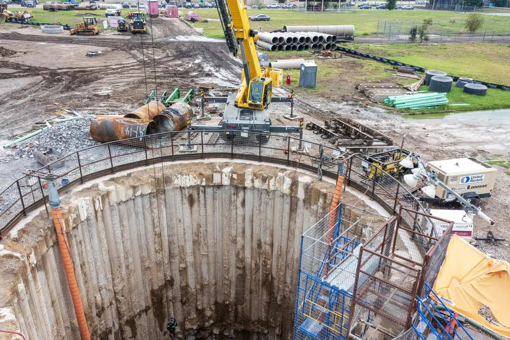
Most of the pipeline for this project was installed by tunneling. The longest tunnel reaches were parallel tunnels for the Bypass Channel siphon, which required dual 720-linear-foot stretches of 60-inch tunnels to be installed in bedrock more than 50 feet below existing grade—driven by very high groundwater conditions and very weak lean clays. To accommodate high ground water, watertight secant pile shafts (with diameters up to 35 feet) were required for the Bypass Channel crossing and the West Fork Trinity River crossing. We also designed a 300 linear foot crossing of an existing earthen levee with an 84-inch steel casing pipe installed by open-shield pipe jacking.
Over the last 15 years, our team has actively collaborated with USACE, the City of Fort Worth, and other stakeholders to deliver more than 15 bid packages, program management, and other support for the FWCC water and sanitary sewer relocations. Set to be completed in 2025, this project mitigated a conflict between segment C of the proposed bypass channel and an existing 66-inch sanitary sewer interceptor. Its unique design also led to the development of a robust siphon design methodology, which fills an industry knowledge gap and is set to enhance future inverted siphon projects throughout the United States.