- October 18, 2021
- Perspectives
On-site Well and Septic Solutions for Industrial Sites

Brandon Guillory,
P.E., LEED AP
Senior Development Services Engineer

Michael Moriarty, P.E.
Water/Wastewater Engineer

Eli Puente, P.E.
Water/Wastewater Engineer
With upfront planning during the site planning process, it is possible to design and implement well and septic systems that allow for opportunities to develop sites that may have previously been deemed undevelopable.
When it comes to a new site, developers want the best bang for their buck. To determine if a site is feasible, civil engineers perform a due diligence/feasibility analysis to identify potential obstacles and determine whether the existing infrastructure can meet the demands of the proposed development. The three most common water and wastewater scenarios related to the site’s location are:
- The site is located inside the corporate limits of a city. In this case, the City typically provides services to the site.
- The site is located within the limits of a Municipal Utility District (MUD). In this case, the MUD is responsible for providing services to the site.
- The site is located adjacent to an existing MUD. In this case, the MUD determines if the site can be annexed into the MUD so they can provide services to the site.
As demand for industrial space has escalated, we are seeing more sites that are neither inside the corporate limits of a City or a MUD, nor adjacent to an existing MUD. There are also sites that are in the vicinity of MUDs, but it is cost prohibitive or infeasible to extend service to a site and request annexation. The good news is that in these cases, there are options that can provide water-wastewater service to a site.
Potential Site Solutions: Well Systems and Septic Systems
Providing water and wastewater service via water wells and on-site sanitary sewer facilities (OSSFs) has proven to be a viable solution for many years. Some sites will have access to—or already have—infrastructure in place for a potable water system, but not a wastewater system or vice versa. Through the due diligence process, we can determine what, if any, infrastructure exists on site and its status (if it is permitted, what the capacity is, where it is located, etc.).
The most important factors for both well and OSSFs are determining the permitting agency and calculating the demand or usage rate of the systems. In Texas, the Texas Commission on Environmental Quality (TCEQ) and local jurisdictional requirements are commonly used to determine the projected water demand and sanitary usage rate based on use of the building and the number of occupants or facilities. This varies by location, so having a local partner who is familiar with the jurisdiction is crucial.
Planning For Well Facilities
When thinking about adding a well facility to your site, there are a few things to consider during the site planning stage:
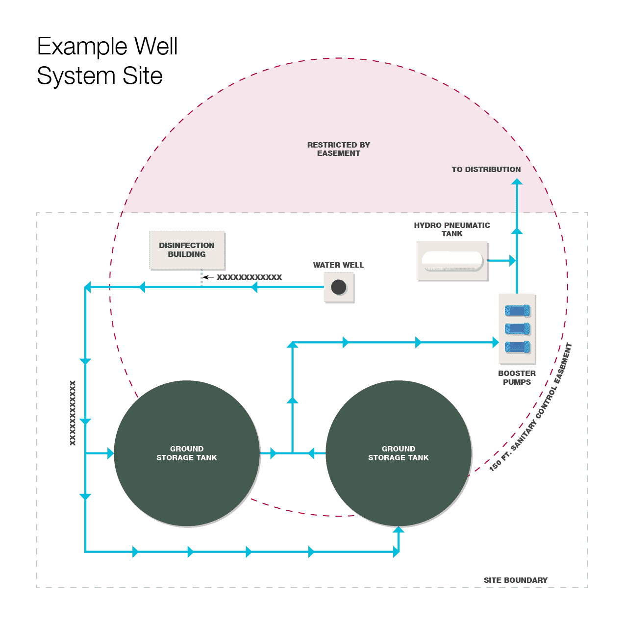
- The example well system illustrated below will take up approximately 0.5 acre of your site
- The well will require a 150-foot sanitary control easement that is centered over the well
- The water plant facilities must be away from wastewater treatment facilities, including septic systems
- Size and cost of the water well can vary depending on water quality and depth of aquifer
- If annual water usage surpasses allotment of subsidence district, a surface water intake or groundwater reduction plan (GRP) would be required to avoid disincentive fees
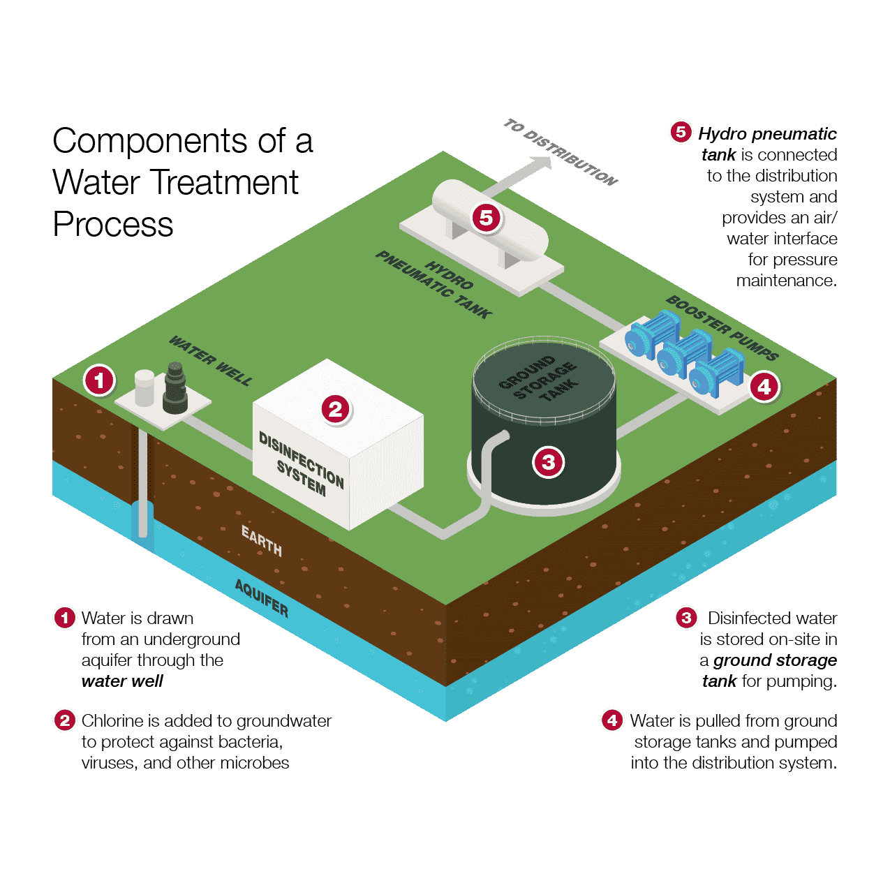
Description of Well Water Treatment System Components:
1
Water Well – The water source for the plant; this can be constructed with a submersible or above-ground motor.
2
Disinfection System – This treats the water from the well to inactivate bacteriological growth. Dosing is typically liquid or gas chlorine for systems with only ground water or chloramine for blended systems. The disinfection system also provides residual disinfection potential to prevent bacteria and other harmful organisms from growing in the distribution system.
3
Ground Storage Tank – Provide storage for the water system to provide water during peak demands. Welded and bolted steel are the most common ground storage tanks, but fiber-reinforced plastic may be available for smaller tanks (50,000 gallons or less).
4
Booster Pumps – High-service pumps for system pressure that draw water from the ground storage tank and pump into the distribution system.
5
Hydro Pneumatic Tank – Pressure maintenance vessel that allows the distribution system to maintain pressure when the booster pumps turn on and off. The tank is filled with water and air; this interface allows the air to contract as pressure in the system fluctuates. This is most common in smaller systems, as larger systems provide pressure maintenance with elevated storage tanks, which are more expensive.
Distribution System – Water line network leaving the ground water facility and extending to water users.
Planning On-site Sanitary Sewer Facilities
When thinking about adding an OSSF facility to your site, there are a few things to consider during the site planning process:
- OSSF systems cannot exceed 5,000 gallons per day (GPD) of usage. If the usage exceeds this, an on-site treatment plant will be required.
- You are only allowed one OSSF per property.
- Separation from property lines, water/drainage infrastructure, and impervious areas needs to be considered when determining the site layout.
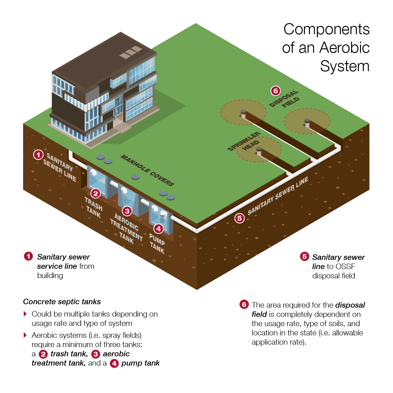
Once you have established that an OSSF will work for your site, it’s important to understand the components of an OSSF so that you design the facility correctly for your site’s intended purpose.
Usage Rate
The usage rate is determined by the type of facility and the number of occupants or facilities. Some common commercial and industrial usage rates (when including water savings devices) are shown in the table below.
Common Usage Rates
| Type of Facility | Usage Rate (GPD) |
|---|---|
|
Factories |
12 (per person per shift) |
|
Hotel/Motel |
60 (per bed) |
|
Travel Trailer/RV Park |
40 (per space) |
|
Office Building |
4 (per occupant with no food or showers) |
|
Stores |
160 (per washroom) |
|
Service Stations |
8 (per vehicle) |
Common OSFF Systems
There are many types of OSSF systems. Some common, along with the suitable soil types, are shown in the table below.
Common OSSF Systems
| Type of System | Suitable Soil Type |
|---|---|
|
Absorptive drainfield |
Sand, Loamy sand, Loam, Sandy clay |
|
Low pressure dosing system or Drip Irrigation |
Sand, Loamy sand, Loam, Sandy clay, Clay |
|
Surface application (spray field) |
Sand, Loamy sand, Loam, Sandy clay, Clay, Fractured Rock |
Disposal Area
The disposal field layout and size can vary and is adjustable. Once the usage rate, type of system, and soil characteristics determined, a disposal field can be sized. As an example of the required area:
- A usage rate of 500 GPD in good soils will require approximately 1,500-5,000 square feet of disposal area.
- A usage rate of 5,000 GPD in clay soils will require approximately 2-3 acres of disposal area.
Questions to Guide Your Planning Decisions
Not every project is the same. While these solutions have been used to successfully develop “undevelopable” sites, a few questions to ask your engineer are:
- Who will you be permitting through (e.g., state environmental agency, PUC, Subsidence Districts)?
- Do you need approval for a well system? If so, how will it affect the design schedule?
- Would the water quality of the well water require additional treatment?
- Does the county have more stringent requirements than the governing environmental agency for an OSSF facility?
- Is the project near an aquifer, thus needing more stringent requirements for an OSFF?
Do you have a site that comes to mind that could utilize these systems? We can provide due diligence reports and quickly analyze your site conditions to see if our solutions will be an affordable option for your project.
About the Authors
Brandon Guillory, P.E., LEED AP
With more than 22 years of experience in civil design and land development, Brandon has extensive experience in taking projects from initial site feasibility and due diligence through preliminary and final design to construction and final punch lists. He works closely with clients and other team members to assure successful projects with creative solutions to complex design challenges.
Michael Moriarty, P.E.
Michael’s professional experience includes wastewater treatment plant, water treatment plant, and pump station design for a variety of projects in both the public and private sectors. He has been the lead design engineer for projects focused on designing and optimizing treatment plants and in the design and selection of pumps, specifically for sites that can be more rural and challenging. Michael has been involved in projects related to wastewater treatment plants, water treatment plants, sanitary lift stations, and storm water pump stations.
Eli Puente, P.E.
Eli is an expert development services and water/wastewater resources. His project experience includes paving and grading design as well as thermal and electrical utility design. Most notably, he has worked on large and small diameter water/wastewater pipeline projects that involve trenchless replacement/rehabilitation methods such as pipe bursting, horizontal directional drilling, tunneling, microtunneling, and horizontal auger boring. He has extensive experience in taking projects from design development through to construction phase services.